This is the first of (hopefully) many devlogs. The format of these should be more casual than my normal posts. By doing this I hope to...
Stay on track. If I know people are reading about my progress, I'm less likely to fall victim to shiny-new-thing syndrome.
Get more comfortable with sharing incremental progress publicly. I often feel the need to make everything I build with the intention of publishing highly polished. Polish is important if you're trying to sell something, but not really all that important if you just want to iterate. And this means iterating both on the piece of work, and on your own skills.
Increase my
"luck surface area".
The idea behind this is that luck is just a function of doing things and talking about those
things (L = T * D). You never know who might get value out of something you're working on, so
just put it out there!
Anyways, that about covers it. Moving on to the particulars...
I'd like to move closer to hardware. There's quite a bit of uncertainty in the software space these days. AI seems pretty effective at one-shotting text-based problems with an easily verifiable result. I'm generally optimistic on the continued existence of SWE as a profession, but I think having more powerful tools means we should start working on cooler stuff, rather than do the same stuff with less people.
My goal is to build some sort of autonomous RC car. RC is a bit of a misnomer here because the end goal is to have all of the computation happen on-board. I use the term RC to suggest it will be small and unmanned. Why then, wouldn't you call it a "drone"? Technically drone means an unmanned vehicle, but colloquially it has come to mean a quadcopter. I just want a small car that drives itself. But I digress.
In school I majored in computer science, but with a focus on systems and computer architecture. Since then, I've worked professionally mostly on build security. Which means that I am: - Decent at writing code generally. - Pretty rusty at writing C. - Pretty rusty with digital circuitry - A complete moron at analog circuitry.
So it remains to be seen whether this goal is possible. At the very least I'll get to learn a lot. But lets go ahead and dive in!
So again, I haven't done much analog electronics. I got an A in Physics 2 in college, and then immediately deleted all of that info from my brain (oops). So bear with me here...
I decided to start with a "hello world" analog circuit, lighting an LED.
So my first attempt was connecting the LED directly to the 9v battery. Nothing happened. Then I tried the reverse direction, a bright flash, and then nothing.
I did some research to figure out what happened. Why does the LED care which direction the current flows? Why did the LED burn out?
As for the first question, I discovered it was due to the fact that an LED is a Light Emitting Diode. A diode is a component that only allows current to flow in one direction. It's like a one way valve. So by definition, it will not work if you don't have it flipped the right way.
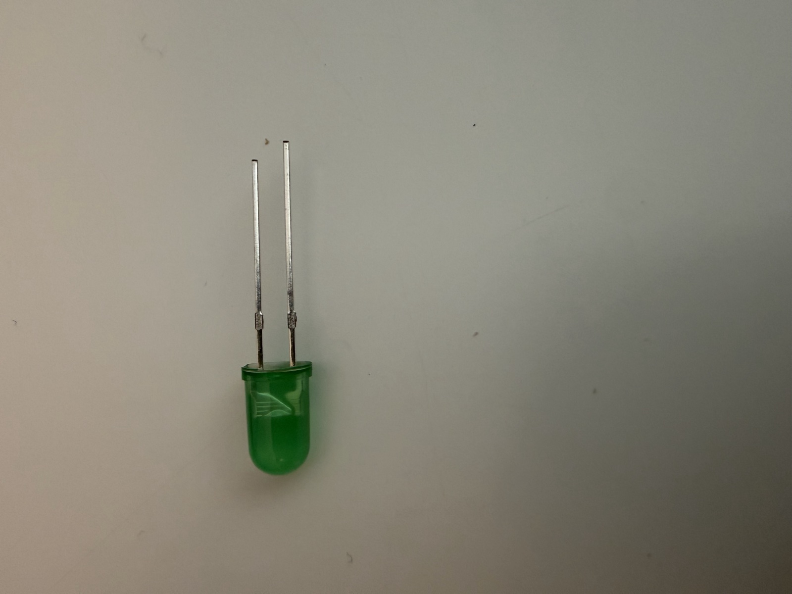
I learned that for LEDs, the anode (the positive + side), usually has the longer lead, whereas the cathode(the negative - side) has the shorter lead. Additionally, within the LED, the anode side is usually bigger and has this "anvil" shape"
Now I needed to figure out why it was burning out. I have a box full of various hobbyist electronics I bought a while back. Resistors, LEDs, breadboards etc. Much of it is not labeled, and I probably wouldn't know what to do with it, even if it was. So there's no telling what kind of LEDs I had my hands on.
Claude suggested I test the LEDs using the diode mode on my multimeter. I gave this a try, but apparently my cheapo harbor freight multimeter couldn't handle my LEDs, so no dice.
Continuing to talk with Claude, we figured out these LEDs are likely white/blue LEDs, but with colored epoxy. The important piece of information here was that white/blue LEDs have a forward voltage(Vf) of 3-3.5 and allow for a max current of 20 milleamps (mA).
What in the world does all that mean? This lead me to (re)learn about Ohm's law:
Voltage(V) = Current(A amps) * Resistance(O ohms)
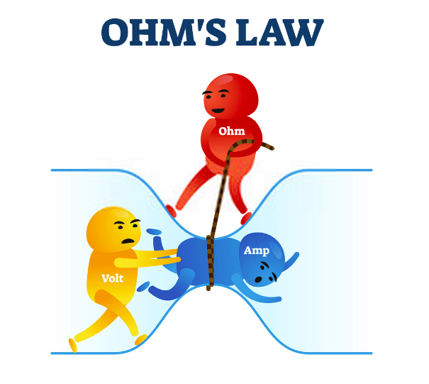
This is typically explained using a water and pipes. Imagine a bucket on a hill, and another bucket at the bottom of a hill connected by a pipe. The voltage is the difference between the amount of water in the top bucket and the bottom bucket. The more you increase the amount of water at the top, the greater the pressure in the pipe will be. The pressure in the pipe is the current, or Amps. One way to increase the pressure is to add more water to one side, another way is to make the pipe skinnier.
With that in mind, what does that mean for our expected LED specs?
The Vf is just a measure of how much voltage is consumed by the component. When electrons flow through the diode, it converts some of those electrons to photons(light), which reduces the forward voltage following the diode. Additionally we need at least 3-3.5V for the LED to work at all. Otherwise it will not allow current through. Our power source is 9V, so we should be good there.
In our situation, the pressure(Amps) in the pipe(the LED) is too great, and the pipe burst. I'm not sure what the resistance of the battery-to-LED-circuit is, but judging from the results, it's likely not high enough, because the LEDs were burning out.
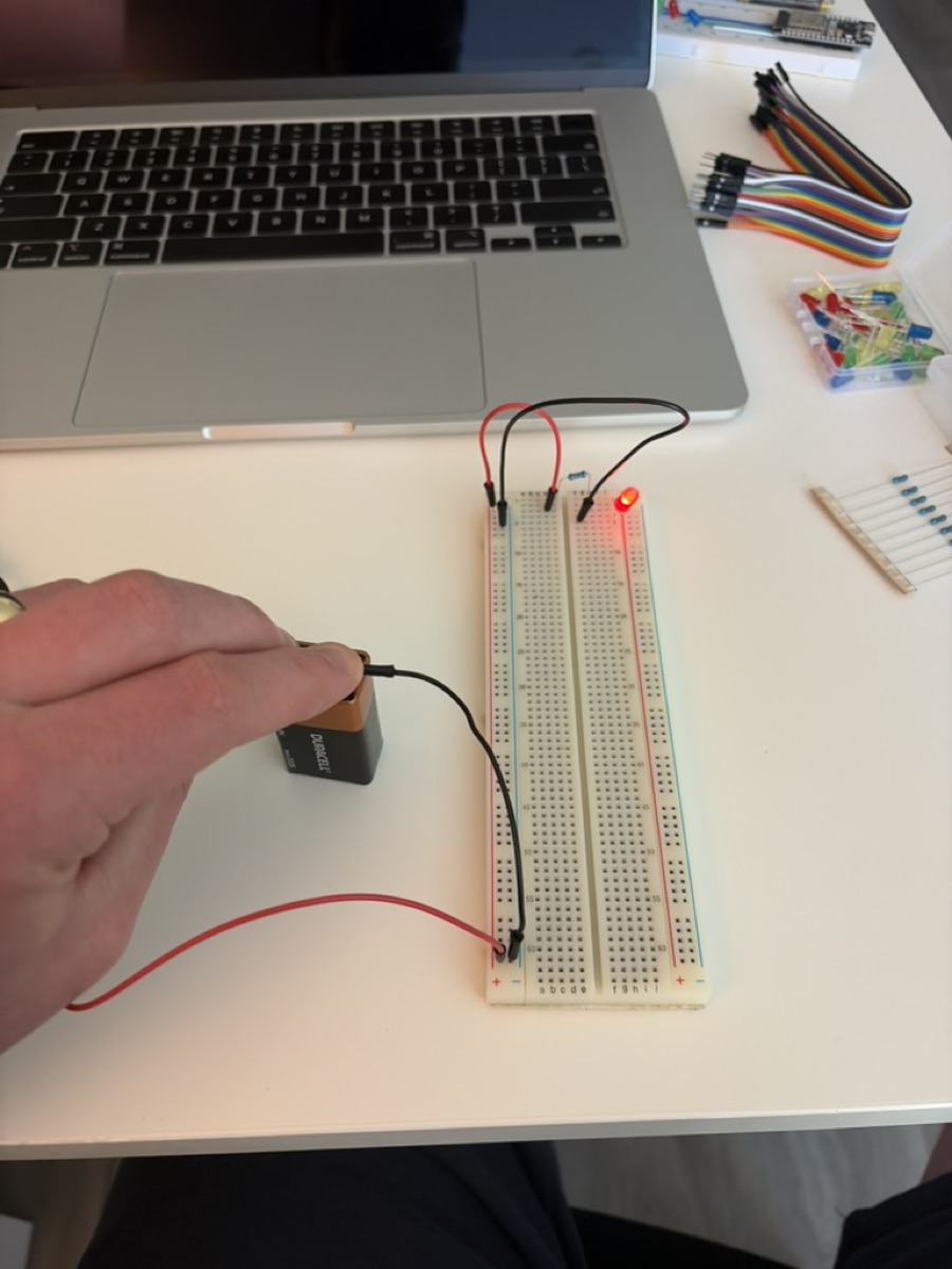
So this meant I needed to add a resistor to the circuit. We know we can have no more than 20mA, and our power source is 9V. So we just need to do the math and solve for the resistance. I ended up using a 1000 ohm resistor, plugged everything in, and we had light!
Now that I'd learned everything I'd ever need to know about analog electronics(jk), I decided it was time to break out my old ESP32 I bought a while back.
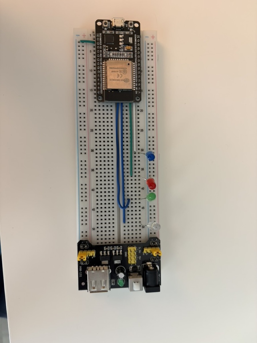
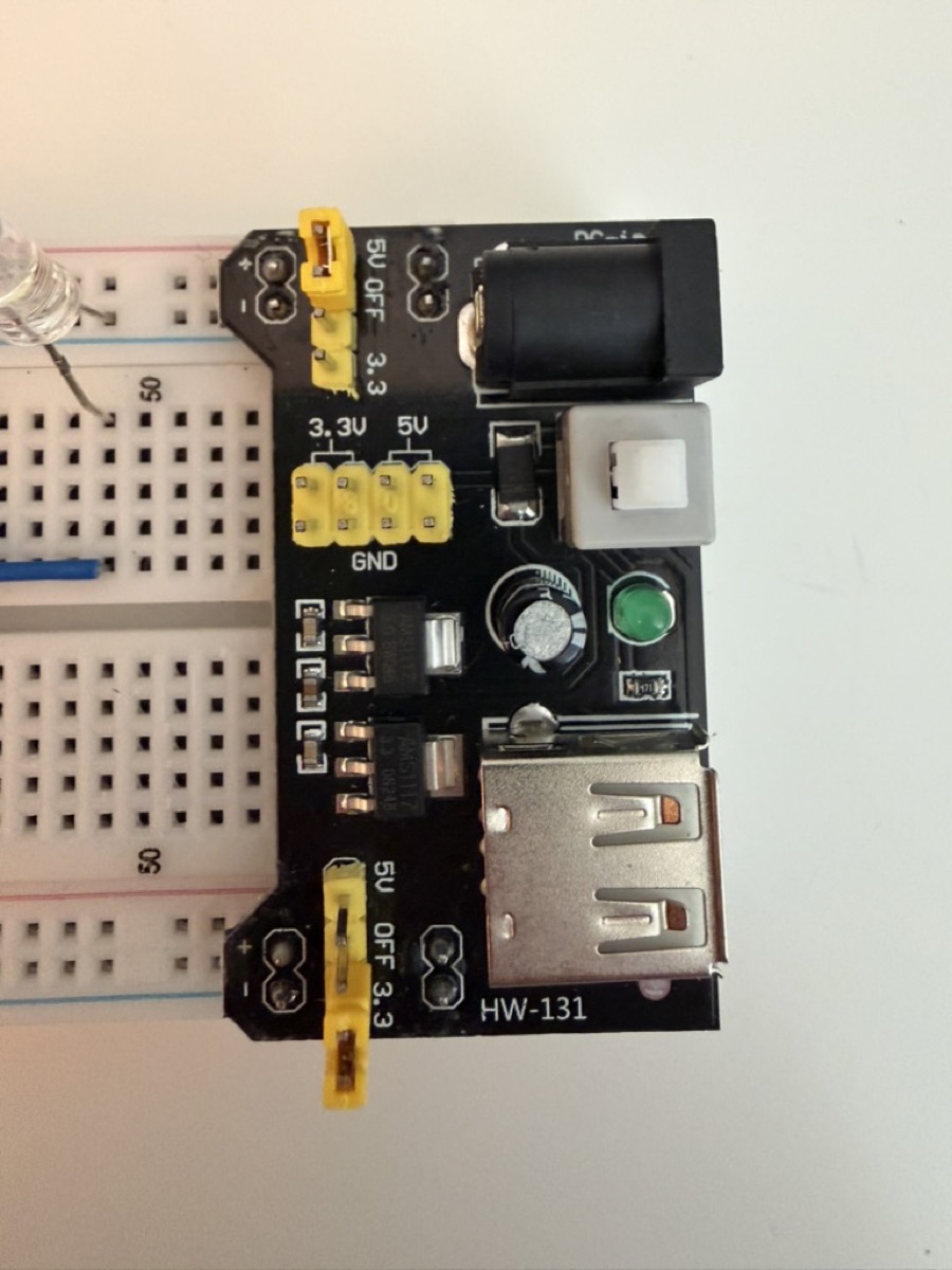
My ESP was on a breadboard hooked up to a handful of LEDs and a power supply. First step was to figure out wtf I was doing way back. The power supply looked like it was configured to use two different voltages. Which is obviously weird. I move the power settings both to 3.3v (which is what the ESP32 wants) and say YOLO and plug it into my laptop. Nothing happens.
I start poking around with my multimeter. The power supply is working as intended. Then I notice the ESP32 wasn't even connected to the positive side on the breadboard power rail. I must not have been using the power supply plugged into the board. I must have been using the direct micro-usb on the ESP32. I unplug the power supply and plug directly to the ESP. Now the ESP turns on, but my LEDs aren't doing anything. That's when I realize what frankenstein hacks I was using on this board. My ESP32 was grounded on one rail, but my LEDs were grounded on the other. The power supply wasn't supplying power, it was completing the circuit. Not sure what I was thinking there. Anywho, I just went ahead and replaced the power supply with a wire, and we were good to go.
I then have Claude spin me up a development environment, since I remember last time I played with the ESP32 it was a bit funky setting up the dev environment, considering it's poorly documented Chinese hardware. I spend enough time thinking about builds at work, I'd rather just have Claude set it up for me. I let him know it was important that I use C (so the Arduino libraries are out of the question), and that I be able to use my text editor of choice, helix (so VSCode + extensions was out of the question). He got me set up with platformio and esp-idf.
The program currently flashed to the ESP made the LEDs flash in sequence. I no longer have that code, so the first step was to re-create that program. So I went ahead and threw together a program, and attempted to flash the ESP.
No dice, I kept getting errors about how there was no device to flash to. Then I went to install some drivers. Still no luck. The ESP wasn't even showing up as a USB device on my computer. It was getting power, but it didn't appear as a device. I tried different adapters, cables, everything in my house which could convert USB C to micro USB. Absolutely nothing worked. I thought maybe it was an issue with my ESP, but the same thing was happening with my (very old) Kindle. Through trial and error I determined it was either a.) a cable issue b.) an issue with my esp. The adaptor should work, my laptop should work.
Seemingly, the most common issue is that many micro-usb cables are charging only, the data pins are not connected. I found this to be unebelievable, considering I had tried every micro usb in my household (7 by my estimation). There was absolutely no way I had 7 charging-only micro usbs!
Despite my incredulity, I went ahead and ordered a USB-C to micro-usb cable. It arrived the same day, and what do you know, it worked. I in fact did have 7 charging-only micro-usb cables. Out of curiosity, I cut open one of the cables, and did only have two wires.
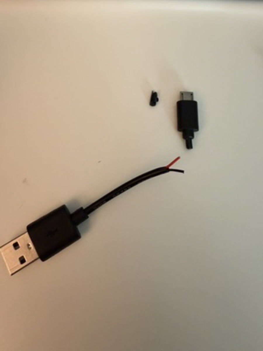
It's been such a long time since I've had a high value electronic device which used micro usb, that I'd lost all my micro usb cables, and they'd all been replaced with crappy ones used to power one-off cheap devices.
After I finally got everything set up, I was able to recreate my old flashed program. It was pretty straightforward, but Claude had me pull in FreeRTOS to handle the timing. I may circle back and dive into FreeRTOS in the future, but it struck me as a bit heavy for my needs. Oh well, I don't care that much at this point.
I tried out a variety of programs just to get my bearings. Ended up settling on a program which displayed a 4-bit number in binary.
Next thing I wanted to do was actually get the vestigial power supply set up, so that the ESP doesn't have to always be connected to my computer.
I looked up in the datasheet to verify the pin I needed, and what the expected voltage was, just to make sure I didn't fry anything. And I added one extra connection between the power rail and the power input pin, and it worked!
Now that the ESP wasn't tethered to my computer, the plan was to connect the ESP via bluetooth and be able to send numbers to the ESP which would be rendered on the LED binary display.
Talked with Claude, and he steered me away from Bluetooth, since it would be a little more complex to implement. This is fine anyway, because long term I'm probably going to be using Wi-Fi anyway.
Claude got Wi-Fi set up, and then I was able to send numbers to the ESP remotely!
I'm definitely going to have to circle back on this code, as I have no idea what Claude has written. But that's ok, this is just a POC.
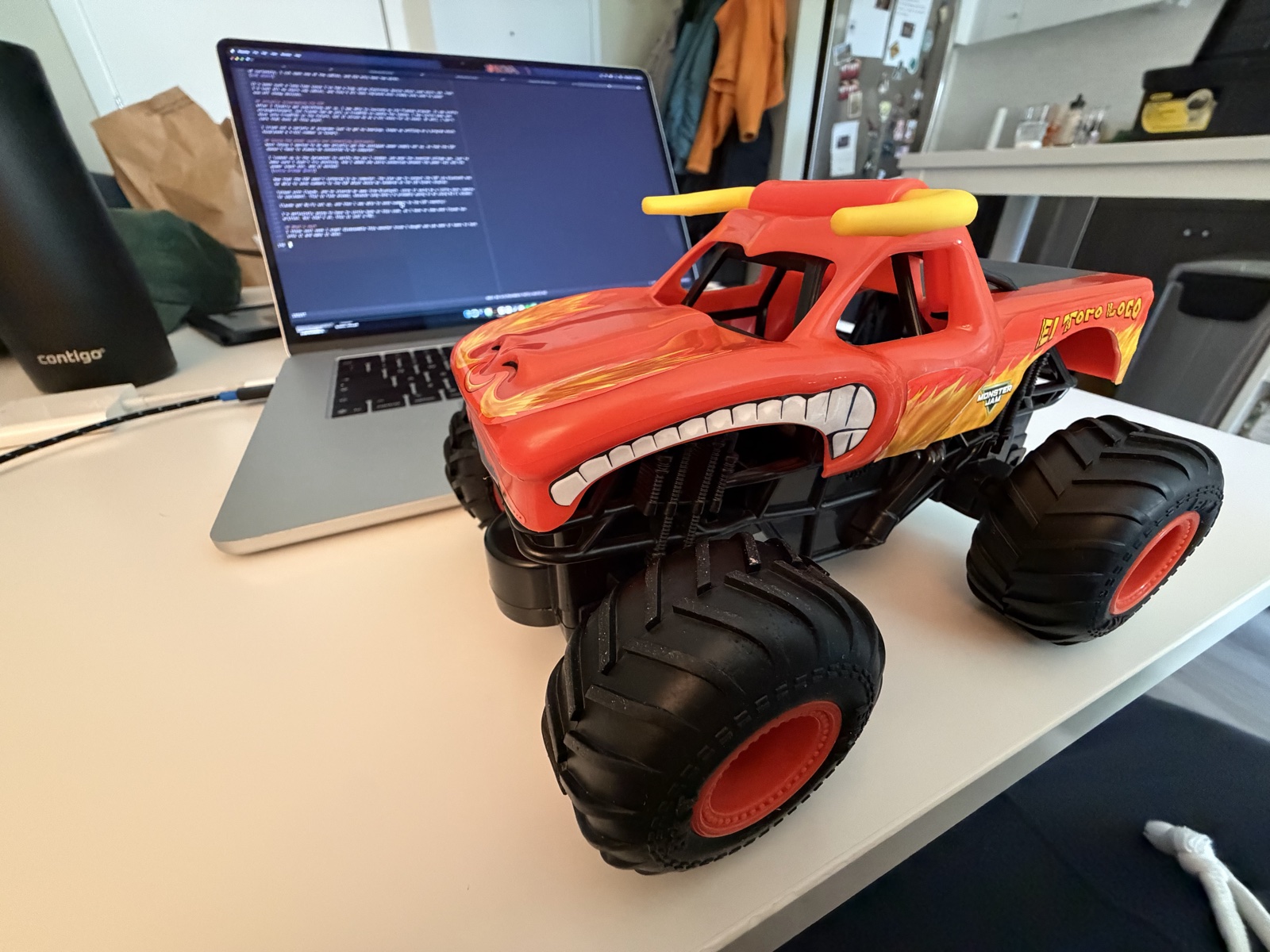
I think next week I might disassemble this monster truck I bought and see what it takes to hack into it and make it move.