Last weekend I successfully set up my ESP32 such that I could control it over WiFi. This weekend, I set out to hook up my ESP to my toy monster truck.
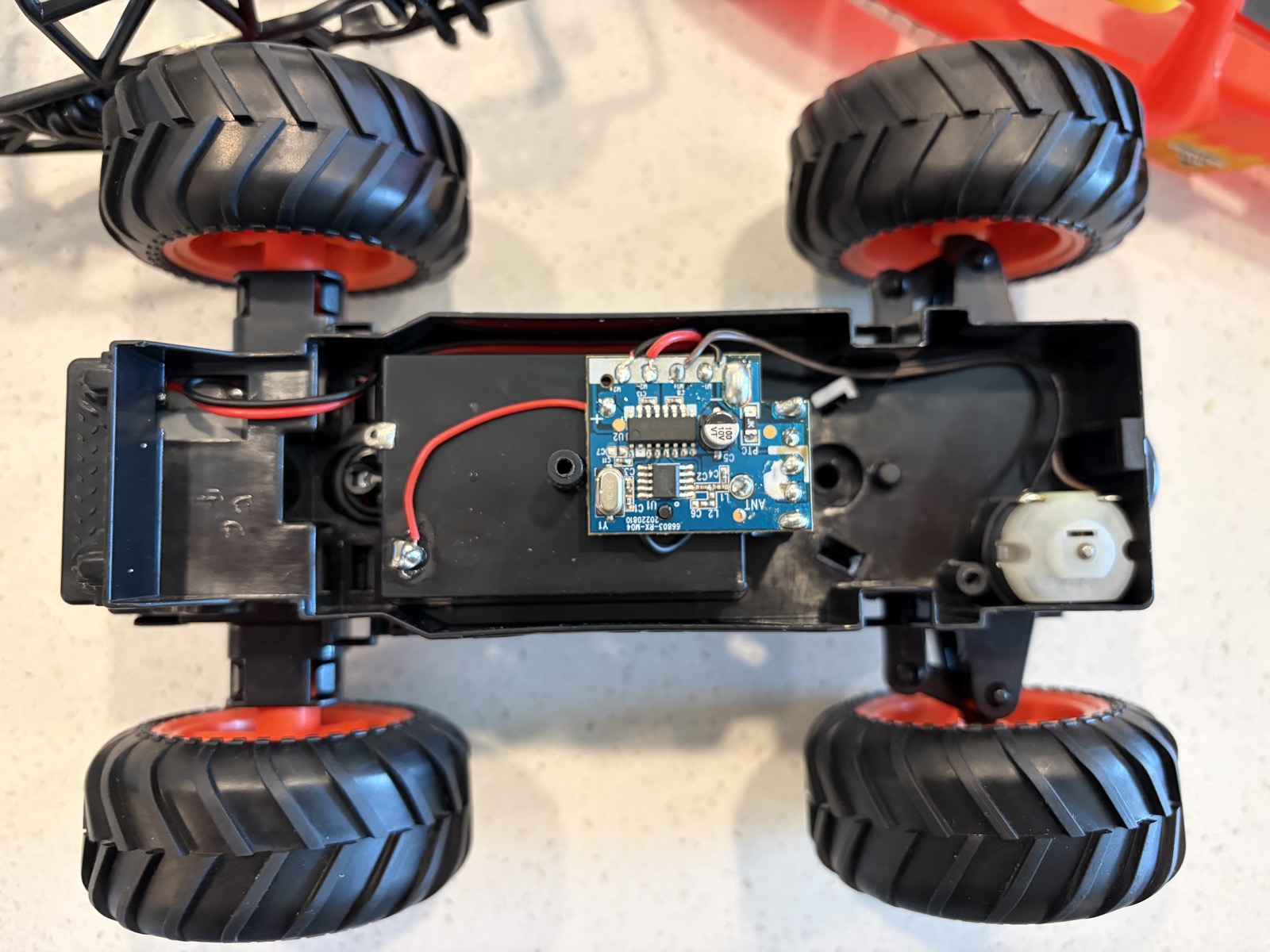
So I went ahead and disassembled my monster truck. It continues to amaze me how cheap this thing is. It's really just a couple motors, a battery pack, and a small circuit board. Nothing else. In particular it surprised me that the steering is not controlled by a stepper motor or a servo, it's just a simple motor that is prevented from rotating freely. Steering in one direction just rotates the motor until it cannot anymore.
the monster truck after disassembly — chassis, motors, battery hookups, and PCB exposed
This was concerning to me because as far as I understood it, providing power to a stalled electrical motor would simply cause the motor to heat up. I started poking around with my multimeter to investigate.
I measured the voltage across both of the motors. I found that the steering motor was being driven at 3.6V. When I turned one direction it was a positive voltage, and when I turned the other direction it was a negative voltage. The same thing happened with the drive motor, negative for one direction and positive for the other. The drive motor had a magnitude of 4.6V.
I also tried to measure the resistance of the motors. When they were not powered, they gave me a resistance of 10 Ohms. When I gave them power, the resistance was not readable. This is to be expected, as the multimeter measures resistance by sourcing a small known test current and measuring the resulting voltage drop. If there is already a voltage being applied to the circuit by the battery, the meter's test current is overwhelmed and it can't make sense of the reading.
Since I couldn't measure the resistance, I was curious about the current. While the steering motor was stalled, I got values which were jumping around from 1-2A. This was surprising to me, I wasn't sure what was happening here. I talked with Claude for a bit, and figured out the source. Earlier, I was confused why the motor wasn't burning out when it was powered but prevented from moving. The reason is that the original RC's controller was applying pulse-width-modulation. The controller was not applying a constant voltage to the motor; it was switching on and off rapidly. This is why the current seemed to be jumping around — the controller was not constantly applying voltage. It was turning the power on and off rapidly in order to protect the motor from overheating.
As an aside: this was the lightbulb moment for me. Just because I can hook together various electronic components in a semi-competent manner and read datasheets doesn't make me an electrical engineer. An electrical engineer designed the motor controller! Likewise, most people could probably make a website if they tried, but that doesn't make them a software engineer. An engineer is expected to work within very strict constraints, while a hacker enjoys a wide margin of error with forgiving tools built by engineers.
Pulse width modulation can also be used to throttle a motor. A duty-cycle is the percentage of time that power is being applied. A 50% duty cycle means we are applying power half the time. So if we want to run the motor half as fast, we apply a 50% duty cycle to it. I'll leave throttling for later, but we know we are going to need to do PWM in order to avoid burning out our motors.
Now that I'd collected information about how the motors behave when connected to their original circuitry, I decided the easiest and best way to install my own circuitry was to throw out the old PCB, and simply connect my ESP directly to the motors. I considered connecting my ESP to the original PCB and controlling it that way, but so much was a mystery about the original PCB that I decided it was more trouble than it was worth.
I de-soldered everything so that I was left with only the chassis, the battery hookups, and the motors. I decided to install my own leads as well, so that I could easily plug everything into my breadboard.
my soldering station, with my dog Peter watching intently
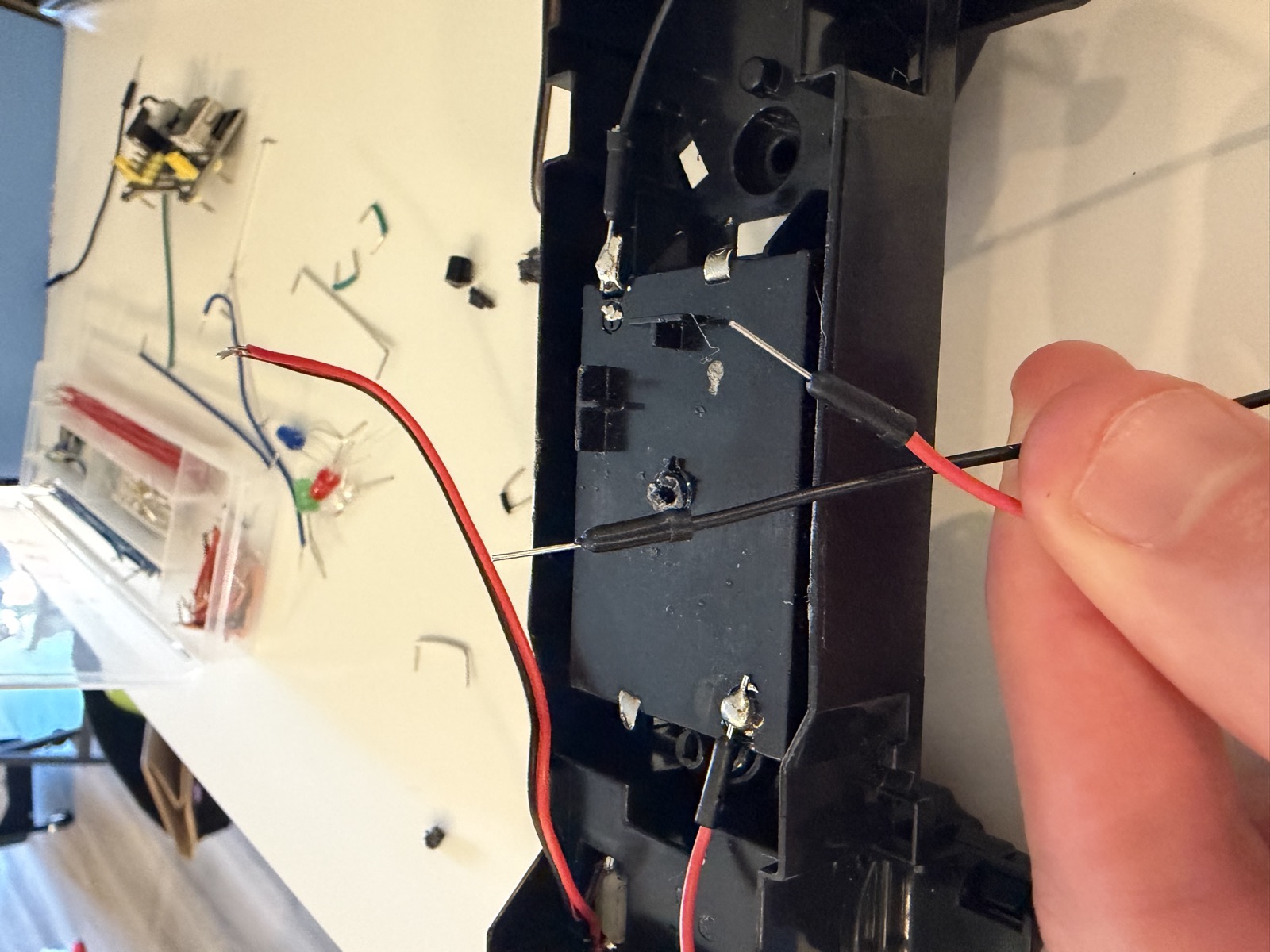
the motors with their freshly-installed leads ready for the breadboard
Now that I knew how the motors could be controlled, I needed to figure out how I could control them from my ESP. My first thought was just to connect them directly to my ESP output pins. But this would not be possible because the data pins on the ESP are not rated for the amps we would need our motors to run at. Additionally, we would need to change the direction of the flow of power in order to steer and drive backwards and forwards. Our data pins, which can only send high and low, cannot do this.
This meant that we needed two circuits. One for our ESP, and one for our motors. I briefly thought I could simply use transistors connected to the data pins of the ESP to direct the flow to the motors. But this would not work for a couple reasons. Firstly, none of the transistors I had were rated to be able to handle the kind of current our motors needed. Secondly, there were some finer details about the behavior of motors which were above my pay grade. Claude suggested that I need a particular IC called a motor controller.
Luckily, since I worked with electronics in college, I already had a motor controller on hand. And doubly fortunately, it had two channels, which could be used to control both of our motors. This controller also gave us the capability to change the direction of current and the duty cycle of the motors. Win-win-win.
Now that I had everything I needed to move forward, I set out to put all the pieces together.
I took my knowledge of my motors and my motor controller to draw up a simple schematic of how my ESP data pins would hook up to my motor controller. This was pretty straightforward.
One issue I ran into was how to power everything. My motors had different power requirements from my ESP. I'd hoped I could power my ESP and my motors using the same battery, but Claude said the on-board 3xAAAs would not cut it for both the ESP and the motors. I decided that I could power my ESP with USB wall power, and the AAAs could power my motors. I figured I could solve the unified power problem in a future iteration.
Additionally, Claude said I might have issues with power sagging with my motors, so I would want to add some capacitors to the motor power.
One final wrinkle was that the motor controller required two sources of power, one for the motor, and one for the controller itself. Fortunately, it accepted 3.3V, the same voltage as the ESP. So I could just piggyback off of the ESP power for the motor controller.
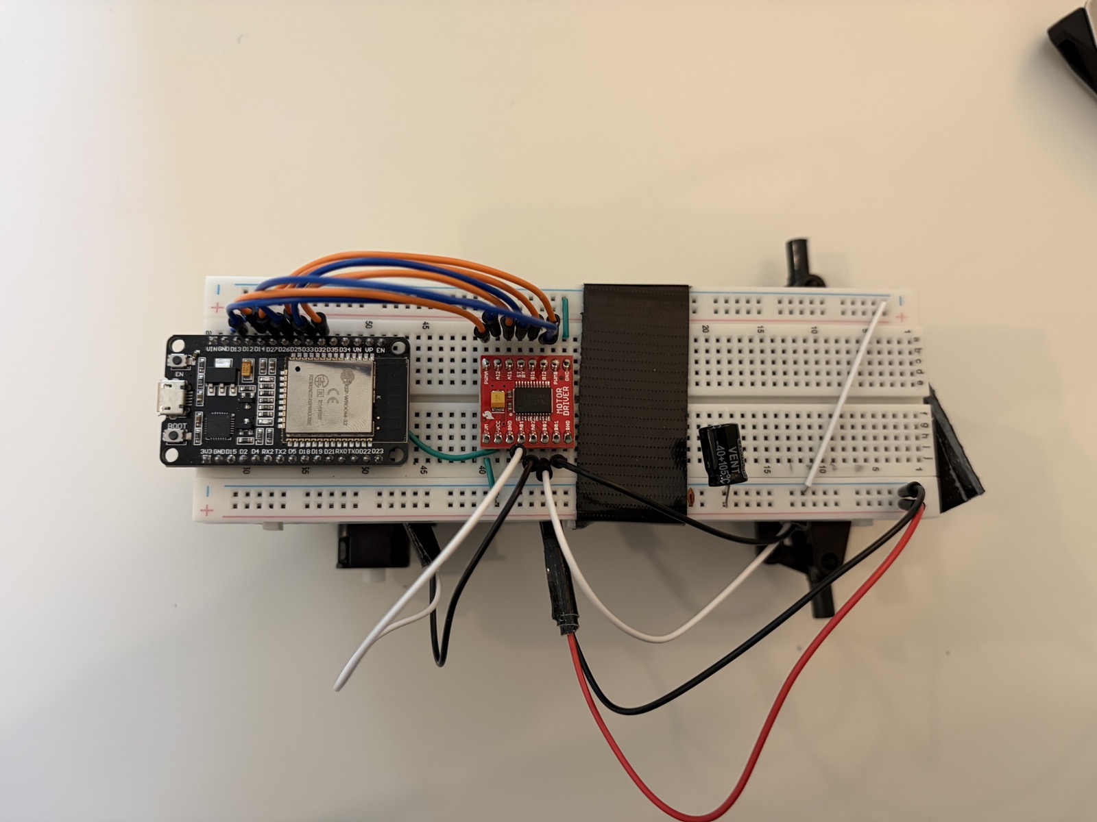
the complete circuit — ESP, motor controller, motors, and battery all wired up. Note I removed the wheels since it got annoying to have my work move around while testing.
I wrote up some code to act as a controller for the car. Basically we just read from WASD/arrow keys, and send a number over UDP to the car. I chose to use raylib for this, since it already handles keyboard input, and I likely am going to want some sort of display for the controls.
I updated the ESP code to output to the correct data pins when it received numbers from the controller.
Now that I had everything wired up and code written, it was time to double check my wiring and do my first test run.
I hooked everything up, booted up my controller, pressed a few keys, and... nothing.
I checked the different controller pins. When I pressed keys, the correct pins were getting set. I checked the motor voltage getting sent to the motor controller. It was 0.6V. Much lower than expected. I talked to Claude about it, and he suggested something was wrong with my capacitors. This was confirmed by removing the capacitors. The car moved as expected. Taking another look at my capacitor setup, it appeared I'd wired them in series, not in parallel — a capacitor in series with the supply line blocks DC, which is why the chip was seeing almost no voltage.
A few smaller tweaks followed: the steering was reversed (easy software flip), the PWM was audible (I bumped it from 5kHz up to 20kHz, above the human hearing range), and the motors were too weak to do much (I'd started conservatively at 25% duty cycle for safety and ended up cranking it to 100% — at our supply voltage and motor resistance, the stall current was still well within the motor controller's rating).
the finished car driving under its own power for the first time. The wheel falling off was to be expected since it wasn't screwed in.
Now that we have a programmable remote control car, the next step is to figure out how to power our ESP using a battery instead of wall power, and make it truly wireless. Additionally, it would be nice to add some sort of sensor. I'm not sure whether we want to hook up a camera or a lidar array. I'm probably going to do some research into the pros and cons of each approach, and figure out which meets our requirements best.